Introduction
The ESP 32 is a low-cost chip with integrated bluethoot and WiFi technology. Not interesting on its own, but can be used to control sensors, servo motors or automated control. In this post, we will focus on the basic steps to program the chip and the integrated development environment we can use to program it and read values from it. More information about the chip can be found on the web, for example Wikipedia or a Google search.
The board we’ll be looking at today is the T-Display-S3 ESP32 with a 1.9″ WIFI display and Bluetooth 5.0. It’s quite an interesting board with a display and the ability to connect to the internet or other bluethoot, making it an ideal platform to display a variety of information.
Installing Arduino IDE
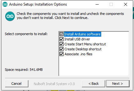
But enough of that introduction, let’s download the development environment. It can be found at Arduino IDE (under Legacy IDE (1.8.X), Arduino IDE 1.8.19, Windows, Win 7 and newer). After downloading the environment, we need to go through the installation process. Click Next. On the selection menu, we need to select everything if not selected
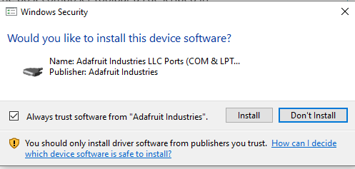
When asked whether to install the usb drivers, install them by clicking “Install”
To configure the board to work with the programming environment, we need to make a few additional settings. These are taken from here
- In the middle, under the Preferences menu, on the Settings tab, in the Additional boards manager URLs field, the following URL must be entered:
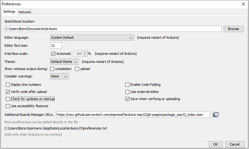
Click OK
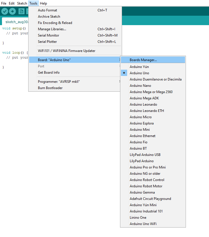
- Look for ESP32 in Tools, Board Manager and install
ESP32(Arduino-ESP32)

- Install esp32 from Espressif Systems
- Copy everything from this git repositories to the Arduino libraries folder (C:\Users\YourName\Documents\Arduino\libraries)
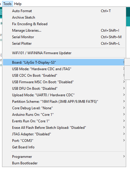
- Select the correct board from the settings. You can choose Tools -> Board -> ESP 32 Arduino -> LilyGo T-Dysplay-S3.
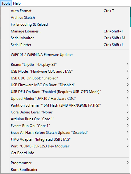
- To complete the setup, we need to adjust a few additional parameters:
| Setting | Value |
| USB CDC On Boot | Enabled |
| Core Debug Level | None |
| USB DFU On Boot | Enabled |
| Events Run On | Core 1 |
| JTAG Adapter | Integrated USB JTAG |
| Arduino Runs On | Core 1 |
| USB Firmware MSC On Boot | Disabled |
| Partition Scheme | 16M Flash (3MB App/9.9MB FATFS) |
| USB Mode | Hardware CDC and JTAG |
On that picture you can look at the settings.
Installation testing
This is where the cool part of things begins. Now we can program the board and experiment with some things. To start with we will run an example and test if it works:
Make sure you choose the right board
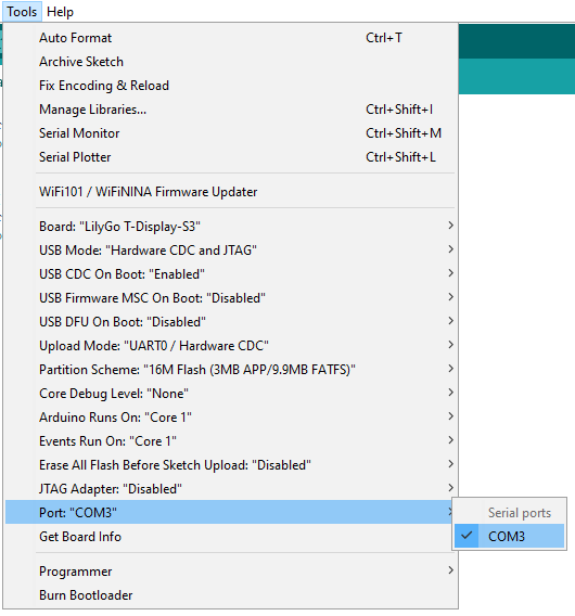
And the correct port:
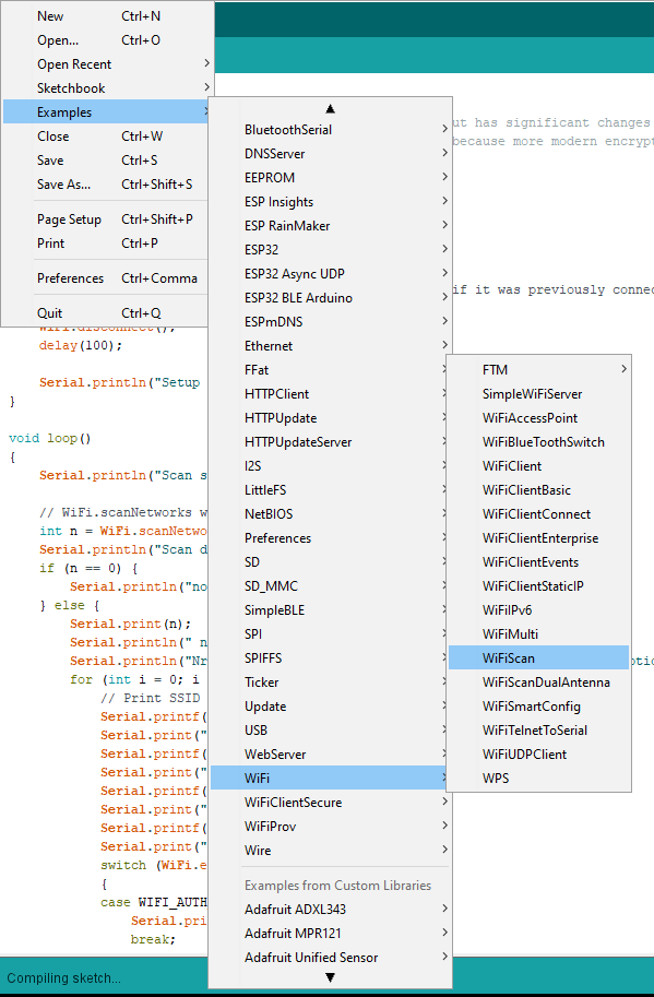
Select from File -> Examples -> WiFi -> WiFiScan
And let’s upload to the board (the button on the top left with the arrow in the circle)
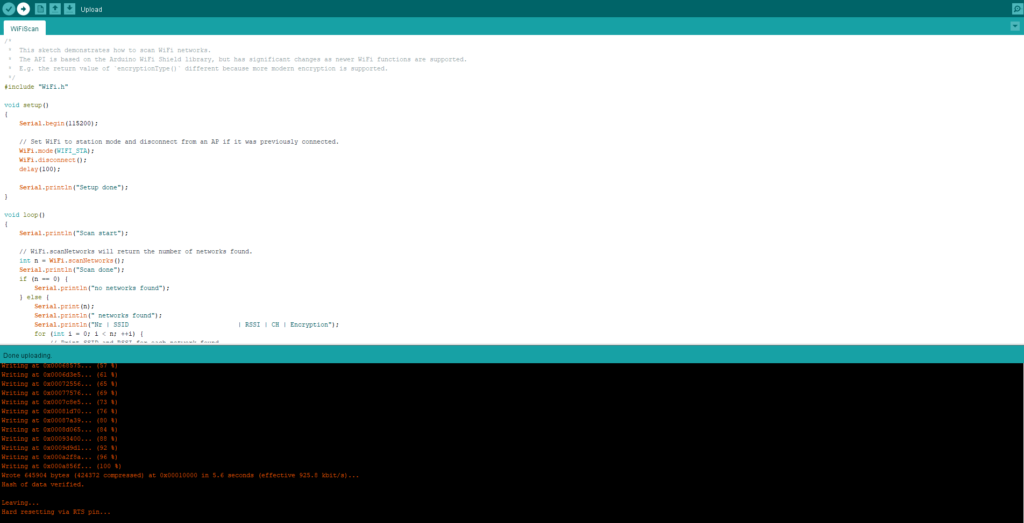
Once the upload is successful you will see
Wrote 645904 bytes (424372 compressed) at 0x00010000 in 5.6 seconds (effective 925.8 kbit/s)...
Hash of data verified.
Leaving...
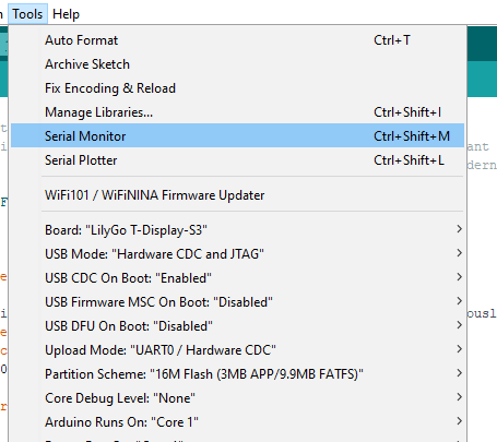
Hard resetting via RTS pin...This means that the code has been uploaded to the board and run. You can see the result by opening the serial console from Tools -> Serial Monitor:
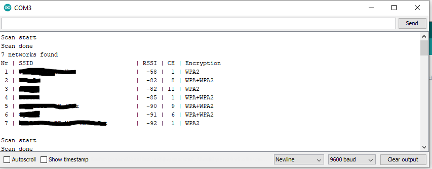
And the result will be:
What next
These were the basic settings of the programming environment that will help you get started with the esp32 board and write self executing code. This way you can create your own project and experiment with the board and code. In the examples section you will find a lot of useful code or ideas what your next microcontroller project could be.
Happy coding!